
Short answer: a bar bending schedule is a cutting list for reinforcement. The number that matters is cutting length, and it is always the same equation: add the arms of the bar, add the hooks, subtract a deduction for every bend. A 90° bend deducts twice the bar diameter, a 135° bend three times, a 45° bend once. Convert to weight with d² ÷ 162 kg per metre. A rectangular stirrup in a 300 × 450 beam with 25 mm cover and an 8 mm bar comes out at 1,364 mm and 0.538 kg.
That is the whole method. What follows is each piece of it — why the deductions exist, what they are for every angle and diameter, and a calculator that shows the arithmetic rather than hiding it.
On this page
What a bar bending schedule actually is
A reinforcement drawing tells you where steel goes. It does not tell you what to buy or what to hand the bar bender. A bar bending schedule is the translation: one row per bar mark, carrying the diameter, the shape, the cutting length, the number of bars and the weight.
Done properly it settles three arguments before they start. The steel order is a number rather than an estimate. The bender cuts to a length someone has checked. And when the invoice arrives, there is a document to check it against.
The reason it gets skipped is that it is tedious rather than difficult. Every bar needs the same five operations, and a modest beam has a dozen bar marks. That is precisely the kind of work worth automating — which is what the calculator below and the app further down both exist for.
The cutting length formula
Every cutting length calculation, for every shape, is one equation:
Cutting length = Σ (arm lengths) + Σ (hook allowances) − Σ (bend deductions)
Where: the arms are the straight runs as dimensioned on the drawing, the hooks are the anchorage tails at the ends, and the deductions account for every change of direction.
The deduction is the part people leave out, so it is worth understanding rather than memorising. A drawing dimensions a bent bar to the outside intersection of its arms — the sharp corner. The steel does not go round a sharp corner; it follows an arc of finite radius. The arc is shorter than the two half-arms it replaces, and the difference is the deduction.
Leave the deductions out and every bar is cut long. On one stirrup that is 96 mm of waste. On the four thousand stirrups in a frame it is roughly 300 kg of steel bought, cut, and thrown away.
a = W − 2c
b = H − 2c
Before any of the above, convert the member size to the size the bar actually follows by subtracting the clear cover c from both faces. A 300 mm wide beam with 25 mm cover gives a stirrup core of 250 mm, not 300 mm.
BBS calculator
Pick a bar shape, set the diameter and dimensions, and the calculator returns the cutting length, the weight per bar and the schedule total — along with the arithmetic it used. Nothing leaves your browser.
Cutting length & bar weight calculator
Five bar shapes · 11 diameters · bend deductions applied automatically
This calculator needs JavaScript. With it switched off, use the bend deduction table, the shape formulas and the unit weight table below — they carry the same numbers in static form.
Need the full schedule, on site?
Get Steel BBS Calculator A1 PRO — standard shape codes, footings to slabs, lap lengths and exportable schedules on Android and iOS.
Bend deductions, by angle and diameter
The deduction is a multiple of the bar diameter, set by the angle of the bend. These are the values in standard Indian detailing practice.
| Bend angle | Deduction | 8 mm | 10 mm | 12 mm | 16 mm | 20 mm | 25 mm |
|---|---|---|---|---|---|---|---|
| 45° | 1d | 8 | 10 | 12 | 16 | 20 | 25 |
| 90° | 2d | 16 | 20 | 24 | 32 | 40 | 50 |
| 135° | 3d | 24 | 30 | 36 | 48 | 60 | 75 |
| 180° | 4d | 32 | 40 | 48 | 64 | 80 | 100 |
Read the table as "per bend". A rectangular stirrup has three 90° corners and two 135° hook bends, so on an 8 mm bar the total deduction is 3 × 16 + 2 × 24 = 96 mm.
These multiples are a detailing convention tied to the standard mandrel diameters for bending. If your drawing specifies a non-standard bend radius, the deduction changes with it — the convention is a default, not a law.
Hook allowance
A hook is the tail that anchors a bar into the concrete. Unlike a bend, it adds length, because it is metal beyond the dimensioned arm.
hook = max(10d, 75 mm)
The 75 mm floor matters on small bars: a 6 mm stirrup calculates to 60 mm, which is raised to 75 mm.
| Bar diameter | 10d calculated | 135° stirrup hook applied | 9d (180° end hook) |
|---|---|---|---|
| 6 mm | 60 | 75 | 54 |
| 8 mm | 80 | 80 | 72 |
| 10 mm | 100 | 100 | 90 |
| 12 mm | 120 | 120 | 108 |
| 16 mm | 160 | 160 | 144 |
| 20 mm | 200 | 200 | 180 |
A stirrup has two hooks, so the allowance is applied twice. The 9d column is the older 180° end-hook convention still seen on plain round bars and on some drawings — use whichever the drawing specifies rather than whichever you remember.
Cutting length by bar shape
Each shape is the master formula with its own arms and bends filled in. d is the bar diameter throughout.
| Shape | Bends | Cutting length |
|---|---|---|
| Straight bar | None | CL = A |
| L-bar | 1 × 90° | CL = A + B − 2d |
| U-bar / cranked | 2 × 90° | CL = A + B + C − 2 × (2d) |
| Rectangular stirrup | 3 × 90° + 2 × 135° | CL = 2(a + b) + 2 hooks − 3(2d) − 2(3d) |
| Crank / bent-up bar | 2 × 45° per crank | CL = L + n × 0.42D − 2n × (1d) |
The crank coefficient
A bar cranked up over a clear rise D travels further than a straight one. The extra is D × (cosec θ − cot θ), which for the usual 45° crank is the familiar 0.42.
| Crank angle | Coefficient | On a 400 mm rise (mm) |
|---|---|---|
| 30° | 0.2679 D | 107.2 |
| 45° | 0.4142 D | 165.7 |
| 60° | 0.5774 D | 230.9 |
Note that D is the clear rise between the two bar levels, not the depth of the member. Using the member depth is one of the more expensive mistakes on this page.
Unit weight of reinforcement bars
Cutting length gives you metres. The order is placed in kilograms, and the bridge between them is the same shortcut used across the steel trade.
w (kg/m) = d² ÷ 162
The exact constant is 162.196 — it is 4 000 000 ÷ (π × 7850), carrying the density of steel inside it. The trade rounds to 162, which costs about 0.12%. The shortcut is a steel rule and does not transfer to other metals.
| Bar diameter | Exact (kg/m) | d²/162 (kg/m) | Per 12 m bar (kg) | Bars per tonne |
|---|---|---|---|---|
| 6 mm | 0.222 | 0.222 | 2.66 | 375 |
| 8 mm | 0.395 | 0.395 | 4.74 | 211 |
| 10 mm | 0.617 | 0.617 | 7.40 | 135 |
| 12 mm | 0.888 | 0.889 | 10.65 | 94 |
| 16 mm | 1.578 | 1.580 | 18.94 | 53 |
| 20 mm | 2.466 | 2.469 | 29.59 | 34 |
| 25 mm | 3.853 | 3.858 | 46.24 | 22 |
| 28 mm | 4.834 | 4.840 | 58.00 | 17 |
| 32 mm | 6.313 | 6.321 | 75.76 | 13 |
| 36 mm | 7.990 | 8.000 | 95.88 | 10 |
| 40 mm | 9.865 | 9.877 | 118.38 | 8 |
The last column is the one used at the gate. A tonne of 16 mm is 53 bars; a tonne of 25 mm is 22. Counting the delivery against that catches a short load faster than the paperwork does.
Preparing a bar bending schedule, step by step
A worked example, carried the whole way through: a single beam, 5 m long, 300 mm wide × 450 mm deep, 25 mm cover, with four 16 mm bottom bars, two 12 mm top anchor bars, and 8 mm stirrups at 150 mm centres.
- List every bar mark. Three marks here. Stirrup count comes from the spacing:
5000 ÷ 150 + 1 = 34stirrups. - Work out the core dimensions. Stirrup core is
300 − 50 = 250 mmby450 − 50 = 400 mm. - Apply the cutting length formula to each shape — straight bars stay at 5000 mm, the L-bars pick up a 400 mm leg less
2d, the stirrups follow the stirrup formula. - Convert to weight with
d² ÷ 162. - Roll up the totals and add a cutting wastage allowance before ordering.
| Bar mark | No. | Cutting length (mm) | Total length (m) | Unit wt (kg/m) | Weight (kg) |
|---|---|---|---|---|---|
| Main bars, bottom — 16 mm straight | 4 | 5000 | 20.00 | 1.578 | 31.57 |
| Top anchor bars — 12 mm L-bar | 2 | 5376 | 10.75 | 0.888 | 9.55 |
| Stirrups — 8 mm rectangular | 34 | 1364 | 46.38 | 0.395 | 18.30 |
Total for the beam: 59.41 kg, or 0.0594 tonnes. Add 3–5% for cutting wastage and the order is roughly 62 kg.
Notice the stirrups. They are the smallest bar on the schedule and they carry 31% of the weight, because there are 34 of them. That is why the stirrup cutting length is the row worth double-checking — an error there is multiplied by every stirrup in the job.
Lap length and clear cover
Two inputs come from the structural drawing rather than from arithmetic, and both change the schedule.
Clear cover
Cover sets the core dimensions, so it feeds directly into every bent bar. These are the nominal values for normal exposure under IS 456; the drawing overrides them, particularly for aggressive or marine exposure.
| Element | Nominal cover (mm) |
|---|---|
| Footing | 50 |
| Column | 40 |
| Beam | 25 |
| Slab | 20 |
Lap length
Where a bar is spliced, the overlap is extra steel the schedule has to carry. Lap length is expressed as a multiple of diameter and depends on whether the splice is in tension or compression, on the concrete grade and on the steel grade.
Commonly specified site values are 50d in tension and 40d in compression — on a 16 mm bar, 800 mm and 640 mm respectively. Seismic detailing and epoxy coated bars both increase the requirement, which is why the app carries separate tools for each. Take the figure from the structural drawing; the multiples above are for sanity-checking, not for specifying.
Where a bar bending schedule goes wrong
| Mistake | Effect |
|---|---|
| Bend deductions omitted | Every bent bar cut long; waste scales with bar count |
| Member size used instead of core size | Stirrups too big, cover lost, bars foul the formwork |
| Hooks forgotten on stirrups | Bars cut short; anchorage not achieved |
| Member depth used as the crank rise | Crank allowance overstated on every bent-up bar |
| Stirrup count taken as span ÷ spacing | One stirrup short on every member — the "+1" is missed |
| Laps left out of the schedule | Steel short at splice locations |
| No wastage allowance | Order matches theory, site runs out |
The two at the top account for most of the money. The one that causes the most site argument is the third, because a stirrup cut short cannot be corrected — it is scrap.
Doing this on site: Steel BBS Calculator A1 PRO
Everything above is a method. The difficulty is not the method, it is doing it thirty times for a frame while the bender waits.
Steel BBS Calculator A1 PRO — listed as Constropedia Steel BBS Calc — is our Android and iOS app for reinforcement work. It covers the schedule this page describes and a good deal beyond it.
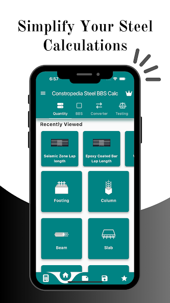
Footings, columns, beams, slabs 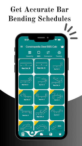
Standard BBS shape codes 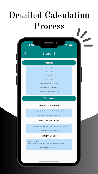
Every formula, substituted 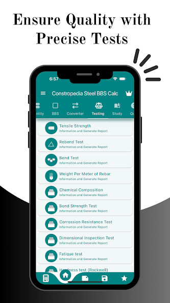
Rebar testing references
What it does
- Bar bending schedules for footings, columns, beams, slabs and retaining walls
- Standard BBS shape codes with dimensioned diagrams — enter the arms and the bar diameter, get length of each bar, total length and weight
- Cutting length and lap length calculations, including dedicated tools for seismic zone lap length and epoxy coated bar lap length
- Reinforcement weight for any element, with total and individual bar lengths reported separately
- Rebar testing references — tensile strength, rebend, bend, weight per metre, chemical composition, bond strength, corrosion resistance, dimensional inspection, fatigue and Rockwell hardness, each able to generate a report
- Study section covering rebar types, size charts for different countries, physical properties, cover requirements, couplers and rebar checklists
- Practice quizzes for engineers learning the method
- Unit converter and an integrated scientific calculator
- Save, share and export — build a schedule bar by bar with "Add to BBS", then send it on
- Customisable themes
It is built for the people who own this problem: civil engineers, construction contractors, site managers and estimation engineers.
Steel BBS Calculator A1 PRO — Android and iOS
Schedules for footings, columns, beams, slabs and retaining walls, with the shape codes and lap lengths already built in.
Frequently asked questions
What is a bar bending schedule?
A bar bending schedule is a cutting list for reinforcement steel. For every bar mark on a drawing it records the diameter, the shape, the cutting length, the number of bars and the weight, so the steel can be ordered, cut and bent correctly before it reaches the formwork.
What is the formula for cutting length?
Cutting length = sum of all arm lengths + hook allowances − bend deductions. The arms are measured to the outside intersection of the bar, which double-counts metal at every corner, so a deduction is subtracted for each bend.
Why do you subtract a bend deduction?
Because a bent bar follows the arc of the bend, not the sharp corner the dimensions describe. Adding the arms as drawn measures a path longer than the steel actually takes, so the difference is deducted. Skip it and every bar is cut too long.
How much is deducted for a 90 degree bend?
Twice the bar diameter, written 2d. On a 16 mm bar that is 32 mm. A 45 degree bend deducts 1d, a 135 degree bend deducts 3d and a 180 degree bend deducts 4d.
What is the hook length for a stirrup?
A 135 degree stirrup hook is commonly detailed at 10 times the bar diameter, subject to a 75 mm minimum. On an 8 mm stirrup that is 80 mm per hook; on a 6 mm stirrup the 60 mm calculated value is raised to the 75 mm minimum.
How do you calculate the cutting length of a rectangular stirrup?
Take the member size, subtract twice the cover from each dimension to get the core size, then apply: CL = 2 × (a + b) + 2 hooks − 3 × (2d) − 2 × (3d). For a 300 × 450 beam with 25 mm cover and an 8 mm stirrup this gives 2 × (250 + 400) + 160 − 48 − 48 = 1364 mm.
What is the unit weight of a 16 mm bar?
1.578 kg per metre. It comes from d² ÷ 162, where 162 is the rounded form of the exact constant 162.196. A 12 m length of 16 mm bar therefore weighs 18.94 kg, and a tonne is about 53 bars.
Why is 0.42D used for a crank bar?
A bar cranked at 45 degrees over a clear rise D travels D × (cosec 45 − cot 45) further than a straight bar, which is 0.4142 D, rounded to 0.42 D on site. At 30 degrees the coefficient is 0.27 D and at 60 degrees it is 0.58 D.
What does Steel BBS Calculator A1 PRO do?
It generates bar bending schedules for footings, columns, beams, slabs and retaining walls, calculates cutting length and lap length, works out reinforcement steel weight, and carries standard BBS shape codes with dimensioned diagrams. It also includes rebar testing references, a unit converter, a study section and practice quizzes.
Which structural elements does the app cover?
Footings, columns, beams, slabs and retaining walls, plus dedicated lap length tools for seismic zones and epoxy coated bars. Each shape code screen takes the bar dimensions, member count and bars per member, and returns length of each bar, total length and weight.
Built by Binary and Bricks — a team of engineers making software for the people who actually build things.